
Results 1 to 9 of 9
-
06-02-2020, 05:44 PM #1jgb@etree Guest
 HELP! Trying to decipher a dirtbike wiring diagram..
So I'm replacing the bars and controls on my sons dirtbike and am trying to use an aftermarket switch I've bought that combines the starter and kill switch into a single unit as the old switches are made for a different handlebar tube diameter and won't fit. Each of the original switches is a two wire connection. The engine stop switch is a toggle - in one position the engine can run, in the other it can not (and instantly dies if running). The start switch is a push button momentary switch - the switch closes for as long as you hold it down until the bike starts. Functions on the new unit are the same, and it has 4 wires - 2 for the kill switch (Orange & Orange/White), 2 for the starter (Blue & Blue/White). Does the polarity/wire order of either switch really matter? Here's the wiring diagram & my way-out-of-my-league-though-process:
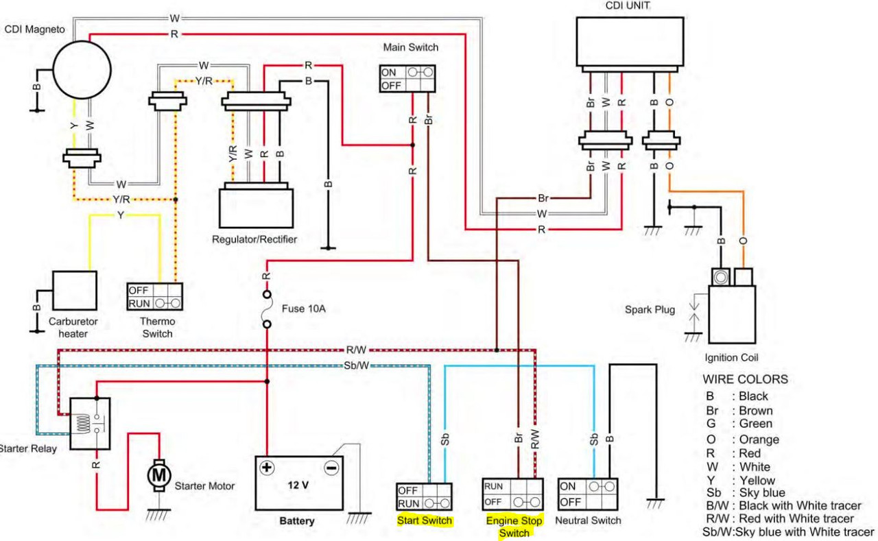
Starting with the start switch (because I think I understand it better) it has 2 wires - Sb & SbW. SbW connects to the starter relay & Sb connects to the neutral switch, which if ON connects to B and completes the ground. I wouldn't think the position of the wires on this switch would really matter here because it's just completing a ground circuit when pressed. I've got myself 90% sure of this, but the remaining 10% leaves me worried as I don't want to spin the starter motor in reverse, although I don't think that is an issue because I'm only completing a ground circuit to the starter relay. It looks like the starter power (which I wouldn't want to reverse) comes direct from the battery and gets directed to the starter by the relay when the Sb/W, R/W circuit I'm looking at is completed. Have I made any completely idiotic and wrong assumptions yet?
I'm less clear on the engine stop switch circuit, but it's also of very little risk/consequence. Worst case it might run in the stop position and not run in the run position and I know that the wires need to be swapped. What really throws me off about this circuit is that the diagram says that the switch is open in the run position, and closed when the kill switch is engaged. From what I think I am understanding it would make much more sense if it were reverse, as that would provide power on the R/W wire to the starter relay giving it the power it needs to flip the relay when the SbW ground circuit is completed by the start switch.
So I've got the starter wiring with Sb & SbW that need to match up with the Bl & BlW on the new switch. My obvious inclination is to connect Sb > Bl and SbW > BlW
On the kill switch side my gut also tells me to connect Br > Or and R/W to OrW.
But I'm far from confident on most of my highly amateur analysis.
Ideas? Suggestions? Ridicule?
Gracias
-
06-02-2020, 08:35 PM #2
 Registered User
- Join Date
- Oct 2014
- Location
- Boston
- Posts
- 32
HELP! Trying to decipher a dirtbike wiring diagram..
I have no experience with dirt bikes or their parts, but usually when I see kill switch, bypass, or cutout wording it is always confusing. The way I’m used to it being described is the ENGINE STOP switch OFF is the normal position (basically normally closed, or the kill switch is off), and in this case RUN means the ENGINE STOP switch is activated (not that the engine is running). Typically the switch wording is generic so there’s only one part number for all the switches and cheaper cost.
They look to be simple switches so polarity shouldn’t matter functionally, but it’s good practice to be consistent. I’m used to seeing switches have a molded identification where position 1 is.
Envoyé de mon iPhone en utilisant TGR Forums
-
06-03-2020, 01:24 AM #3
 ~~~(oYo)~~~
- Join Date
- Feb 2005
- Posts
- 19,346
I can totally help you with this. I was stranded in Hatch, NM with this issue coming back from the mexican border in AZ after I found out my GF was cheeting. Do you want it to run, or function as designed? It still took me 2 days to get home after a hail storm and much deeper shit (mother died, left bike in Taos), but, I made it run. And function. It would require a multimeter and a phone/video call. Glad to help. Life shit, glad to pass on the knowledge.
Short answer, you can ground out the kill switch and you are ready to face a better fate than I did.
-
06-03-2020, 04:23 AM #4
 Registered User
- Join Date
- Feb 2013
- Posts
- 959
Hook it all up as described; you have a good understanding of the circuit already. Check yourself with the labeling of the switches. If the kill sw is backwards, or it won't start, swap wires.
Sent from my Pixel 3 using Tapatalk
-
06-03-2020, 08:53 AM #5jgb@etree GuestSo when the kill switch is in the Run position (as in the bike can be started, etc) the circuit is complete, and then toggling to the kill circuit completes it? That makes a hell of a lot more sense I was getting hung up on the words used in the diagram. Based on that information, the circuit also makes more sense to me now. The Br wire comes from the Main Switch (key) and allows 12V from the battery/stator/rectifier circuit to flow to the kill switch when the key is in the ON position. When the electricity gets to the kill switch, if the switch is in the RUN position (described as OFF in the wiring diagram) power passes thru the kill switch and leaves on the R/W wire to complete the hot leg of the starter relay activation circuit. And then pressing the start button (assuming the neutral switch is in ON position) completes the circuit, energizes the relay and allows 12V to flow to the starter until the start button is released. Although this leaves me some question about how engaging the kill switch (breaking the hot leg of the starter relay activation circuit) kills a running engine as the starter isn't being used? Actually, I see the wire junction on R/W where another Br wire feeds the CDI box. So it looks like the kill switch provides power to BOTH the CDI (the engine computer) and the starter relay circuit, so engaging the kill switch isn't just de-energizing the hot leg of the starter relay, but also the CDI!
 Originally Posted by johnmtl11

Ah-fucking-ha! At least I now think I have a pretty decent grasp of how the circuits work! Thank you! Doesn't give me much clarity on the wire positions (unmarked on the new switch I am installing) but leaves me more confident of my assumption that at best the wire positions are irrelevant, and at worst mistakenly reversing them will not cause any damage and will be pretty damn obvious and easy to rectify.
-
06-03-2020, 08:58 AM #6jgb@etree GuestLooking to keep original function, but see how it would be pretty easy to jumper the two legs of a kill switch circuit to ensure it always runs. You'd just need another method of turning off the bike in an emergency. Which gets me thinking... maybe I should just jumper it as it appears to be a redundant switch that could be controlled by the main switch (key). Originally Posted by MakersTeleMark
I think I have a nice fluke multimeter around somewhere, but have never really taken the time to learn howto use it. The only times I have ever used it have been in situations where diagnostic steps have told me to "set the multimeter to such and such, and to touch the probes to contact x & y and the reading should be this". I'd definitely love a crash course. I'll dig up the multimeter and drop you a PM and see if we can figure something out. Thanks.
-
06-03-2020, 08:59 AM #7jgb@etree GuestI'm just massively overthinking this, huh? I've suspected that could be the case. Appreciate the input. Originally Posted by tango uniform
-
06-05-2020, 01:19 PM #8jgb@etree Guest
Got it! Thanks for the ideas/advice. Either polarity doesn't matter (which makes sense) or I hooked 'em up right the first time. :fkna:

-
06-05-2020, 01:50 PM #9
Registered User
- Join Date
- Feb 2013
- Posts
- 959
Awesome! Originally Posted by jgb@etree
You did not over think my friend. A little trepidation, when not 100% sure, is being safe.
Sent from my Pixel 3 using Tapatalk

 Reply With Quote
Bookmarks